Contents
Selected projects
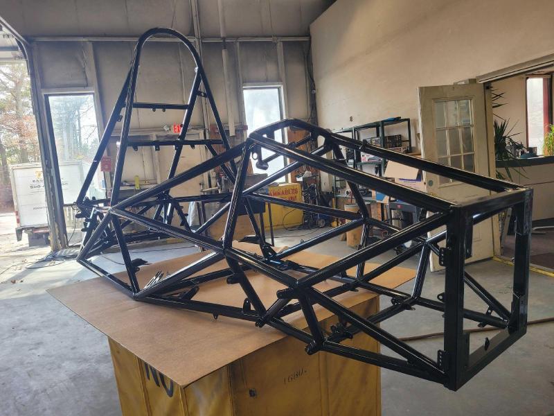
01 · FSAE Space Frame
Redesigning a Formula SAE Space Frame for Four-Wheel Drive
Led the MY25 frame redesign for four-wheel drive: 18% lighter, and stiffer than our model predicted.
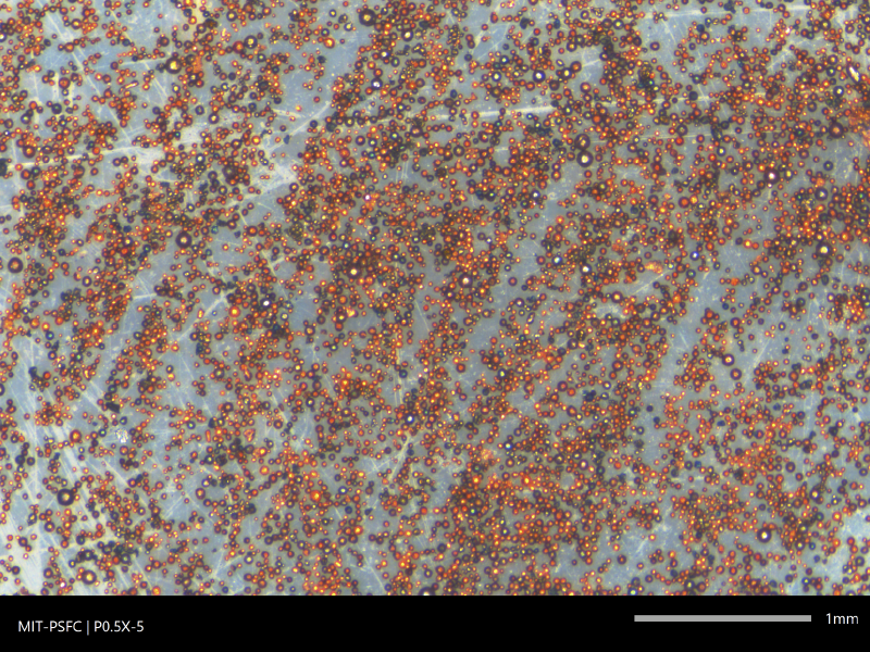
02 · PSFC Gas Atomizer
Making Metal Powder In-House to Prototype Fusion Reactor Alloys
Helped design and build the lab's first high-pressure gas atomizer, making alloy powder for fusion research at a fraction of commercial cost.
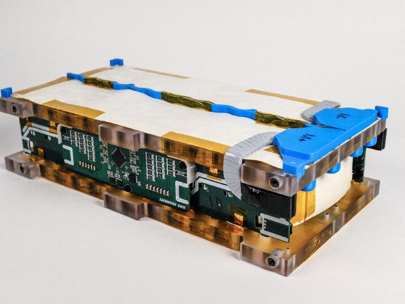
03 · FSAE Battery
Design of MY26 Battery Pack
Co-led the team's first 600 V pack: the most energy-dense in team history, in its first carbon fiber battery box.
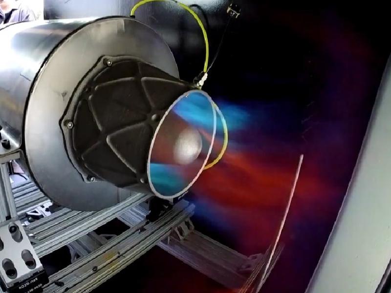
04 · JARVIS Turbojet
Mean-Line and Compressor Design for a 3D-Printed Turbojet
Led cycle analysis and compressor design for a clean-sheet turbojet that won 1st prize in MIT's de Florez undergraduate design awards.
01 · MIT Motorsports · Formula SAE
Redesigning a Formula SAE Space Frame for Four-Wheel Drive
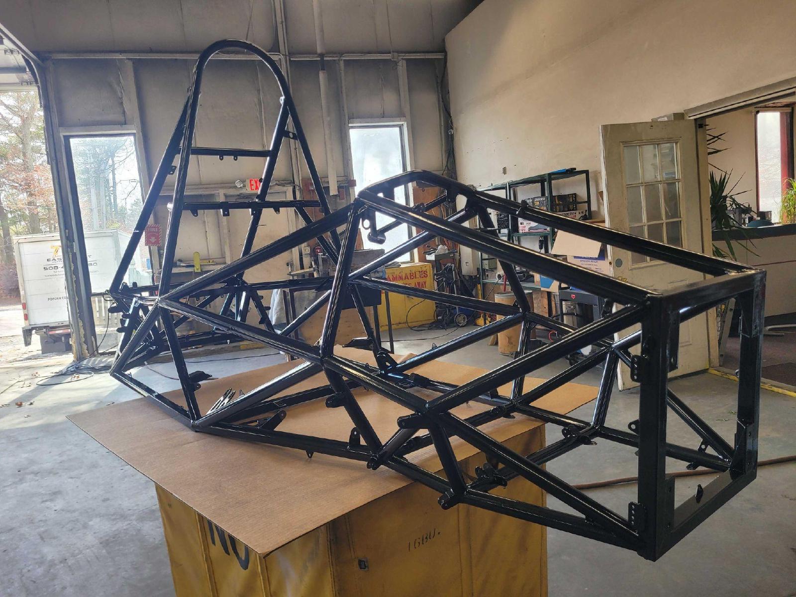
As frame lead, I redesigned MIT Motorsports’ steel space frame for the team’s first four-wheel drive car, with decoupled suspension. The MY25 frame was 18% lighter than MY24 and stiffer than our test-correlated model predicted, and the car placed 9th of 100 teams at Formula SAE Michigan 2025.
My contribution
- Led a four-person team through the MY25 frame’s design, build and testing
- Correlated a 1D FEA model to torsion tests and used it to design MY25
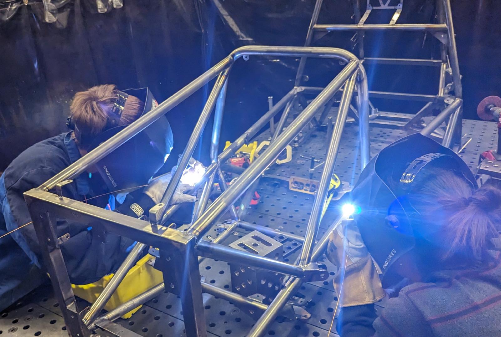
- Learned TIG welding and welded MY24 as one of the team’s two welders
01 · FSAE Space Frame
A new layout for four-wheel drive
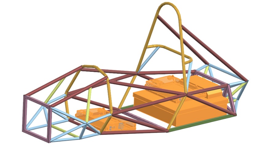
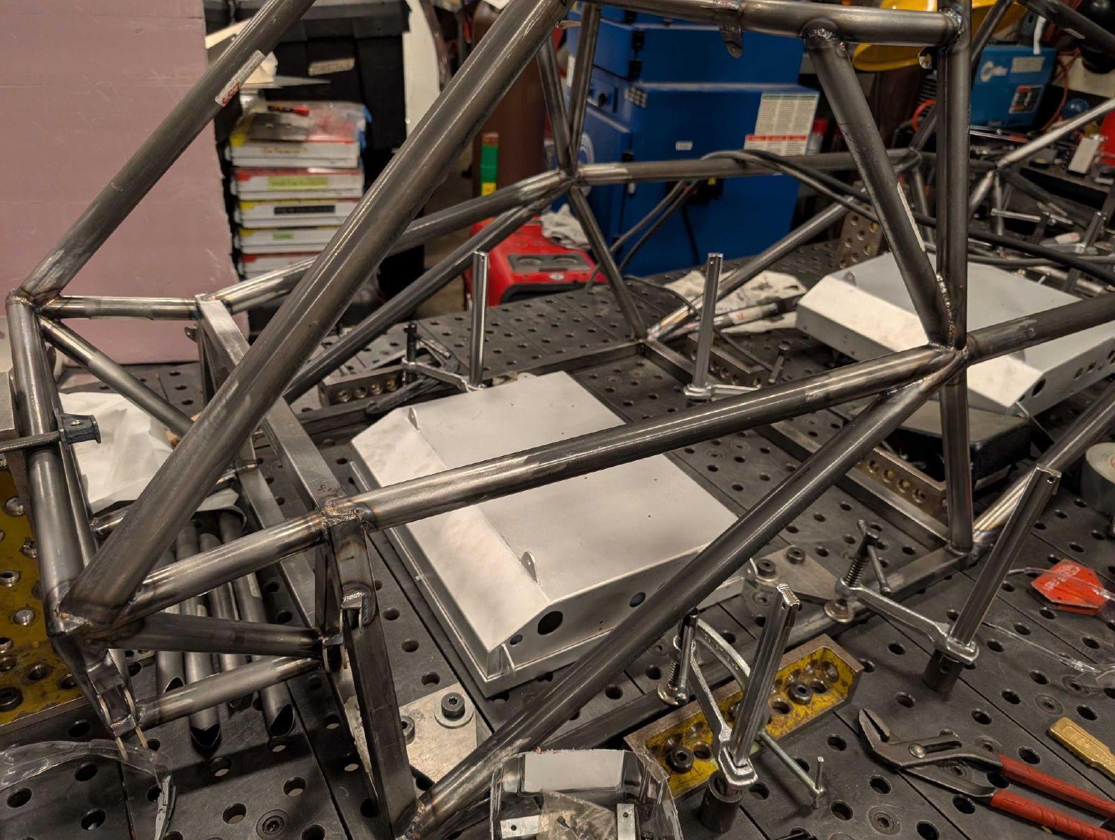
Four-wheel drive and decoupled suspension called for a new frame layout, not an update of MY24.
- 31.3 kg, down from 38 kg
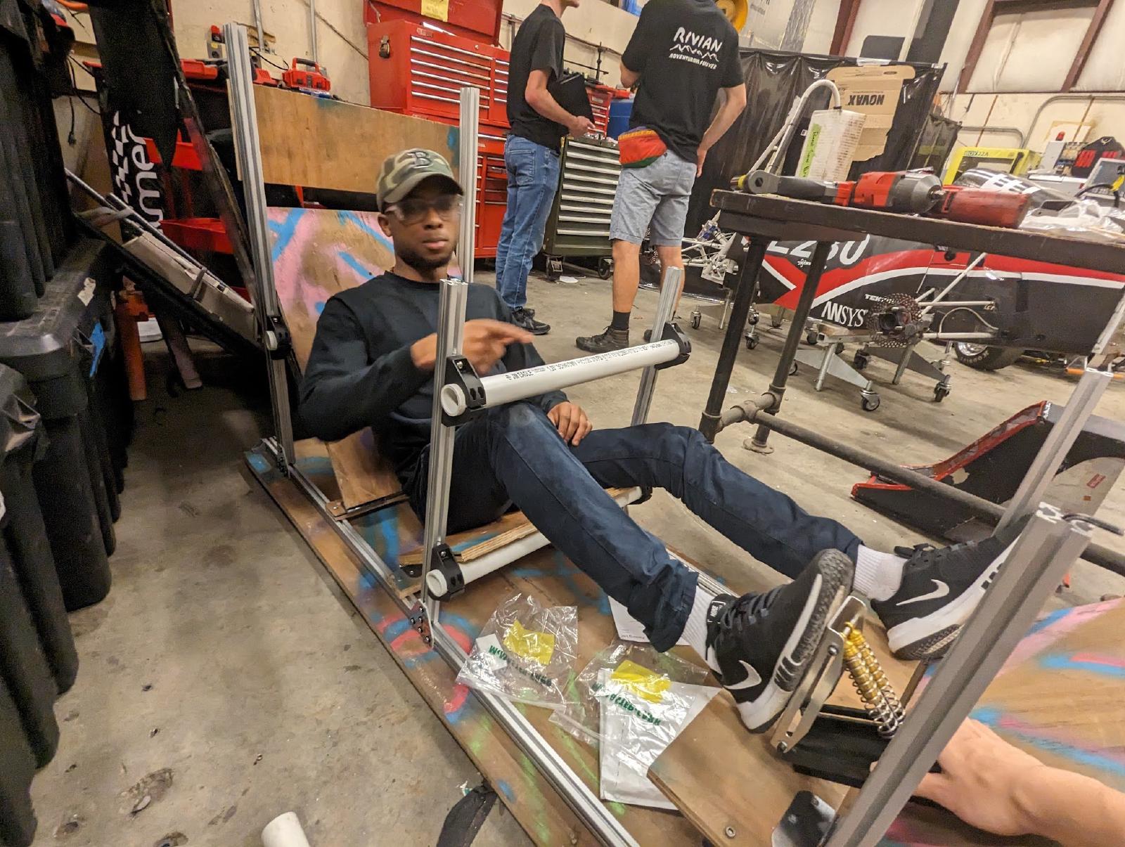
- Lap-sim trade studies and a full-scale ergonomics jig set the layout
- Jigged and TIG-welded in house, with suspension points within ±0.1 in
01 · FSAE Space Frame
Validated by torsion testing
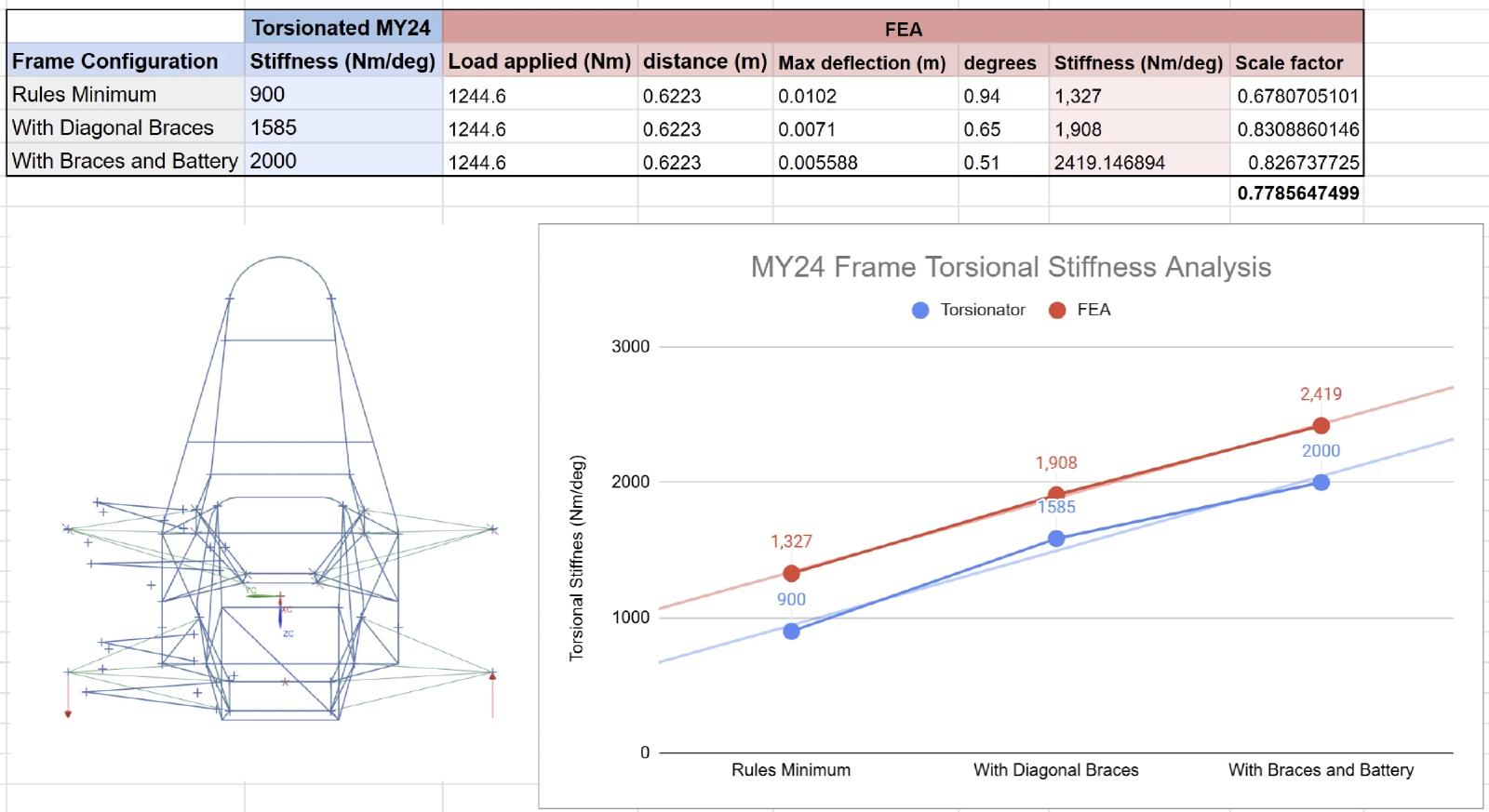
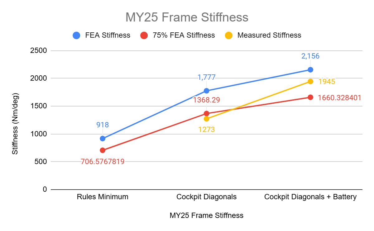
I correlated a 1D FEA model to MY24 torsion tests: measured stiffness was 68–83% of the prediction, and the model ranked every configuration correctly.
Scaled the same way, it predicted MY25 at 1,660 Nm/deg. The finished frame measured 1,945 Nm/deg, 17% stiffer than predicted.
02 · MIT Plasma Science and Fusion Center · Research
Making Metal Powder In-House to Prototype Fusion Reactor Alloys
I helped design and build the lab’s first high-pressure benchtop gas atomization system, which makes 20–100 µm alloy powder for additively manufactured fusion reactor parts, saving over $500/kg and the lead times of commercial suppliers. I presented the work at two conferences, and a paper is in revision.
My contribution
- Designed the converging–diverging atomization nozzle using compressible-flow analysis and CFD
- Built a schlieren imaging system to see the gas jets in real time
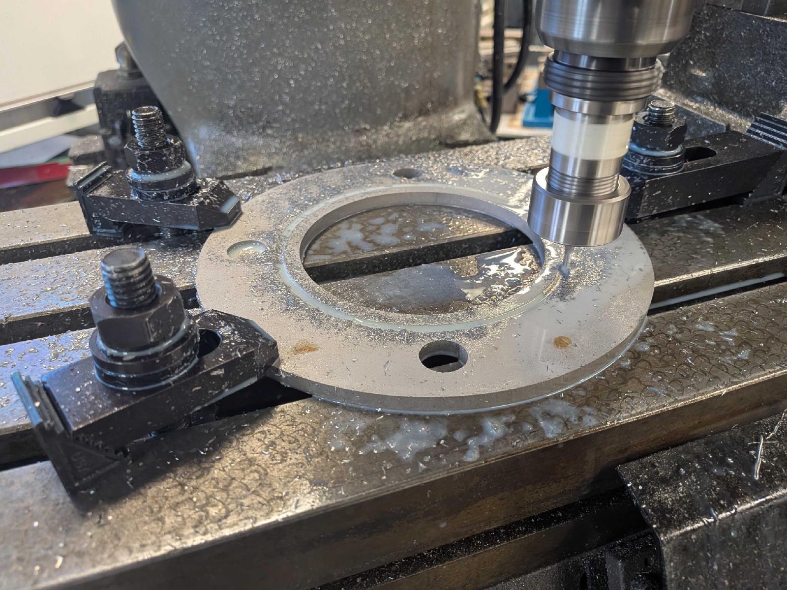
- Machined custom vacuum adapters and integrated the nozzle block with the furnace

02 · PSFC Gas Atomizer
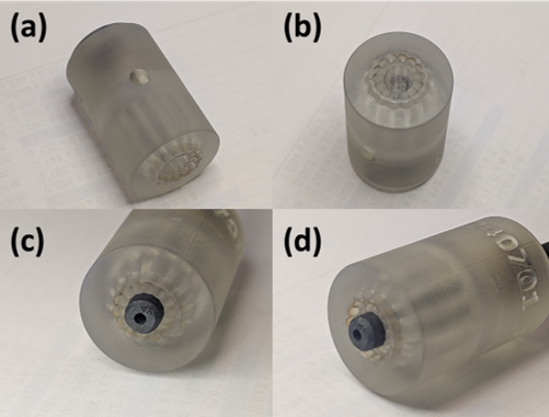
Supersonic nozzles, sized and printed in house
Finding copper alloys that survive in a fusion reactor means testing many compositions, and buying each as commercial powder is slow and costly.
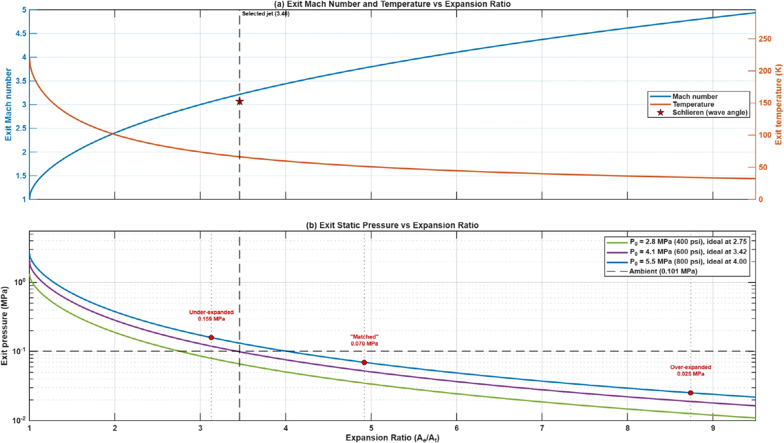
I sized the nozzle’s expansion ratio for the target exit Mach number, then SLA-printed it. Schlieren images of the jet’s shock structure matched the predicted Mach number.
02 · PSFC Gas Atomizer
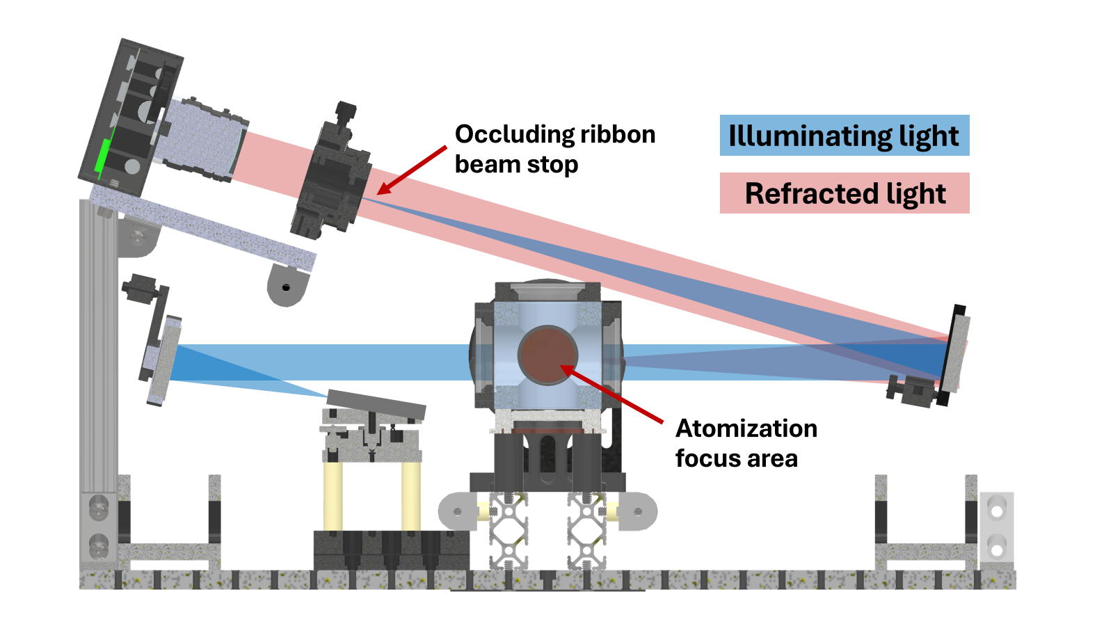
Seeing the flow and building the system
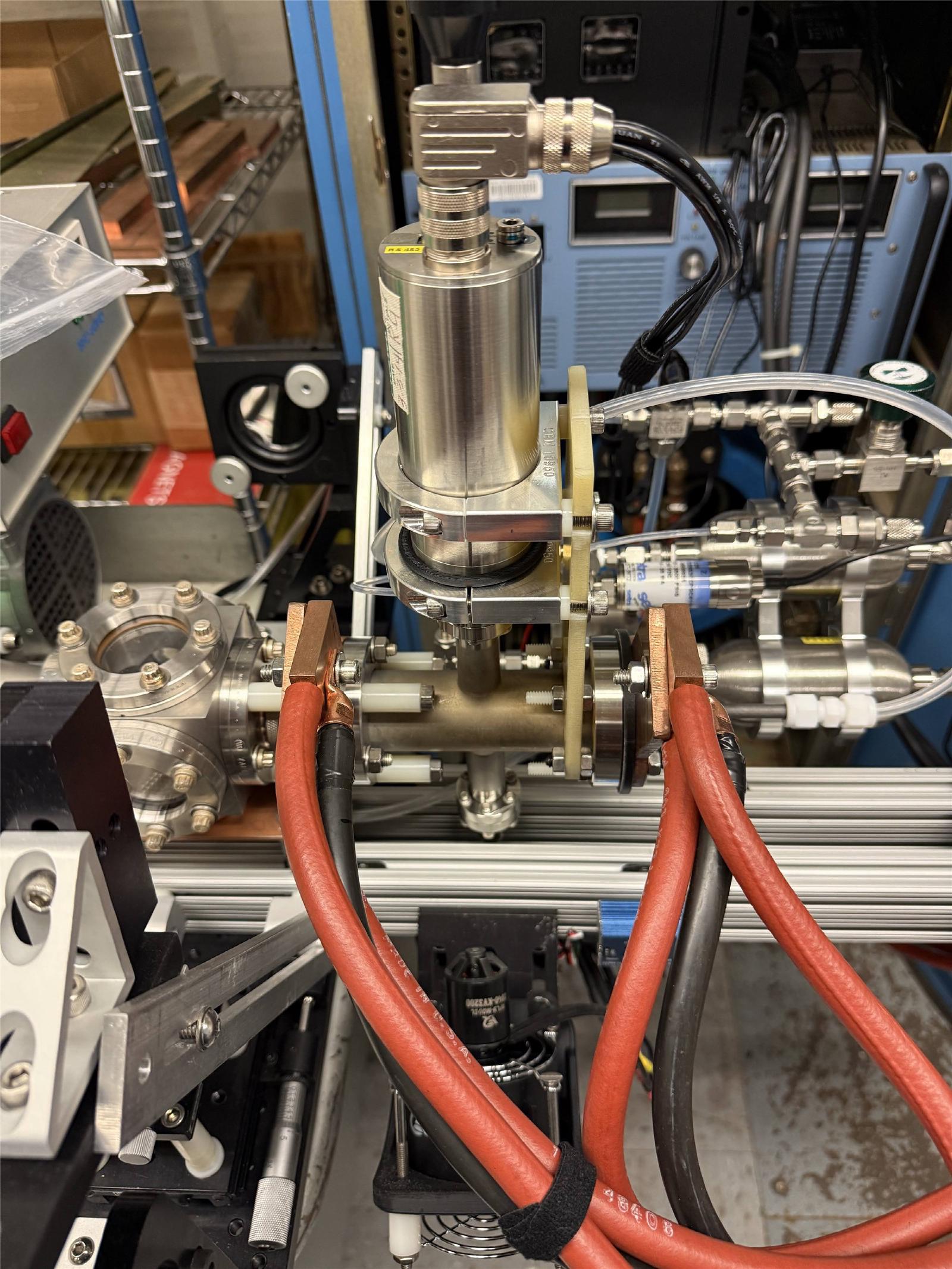
A schlieren system makes the supersonic jets visible so each nozzle can be checked in real time.
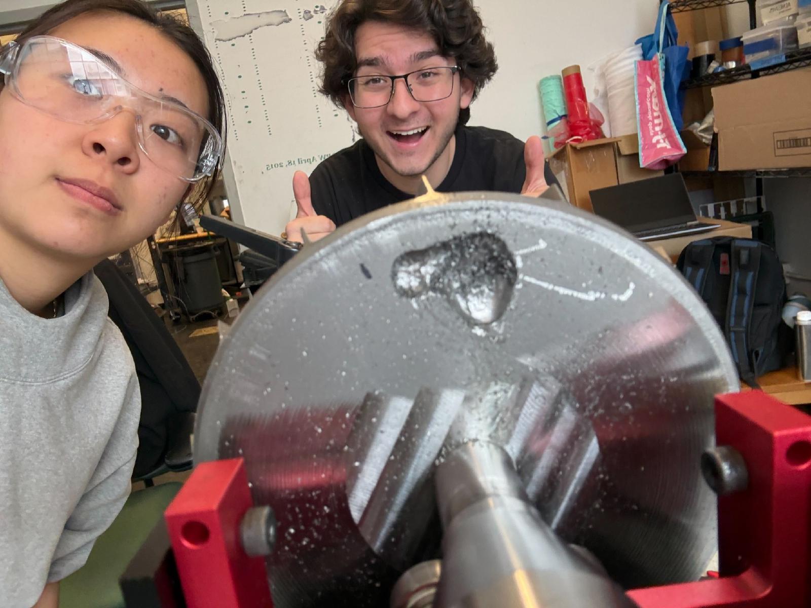
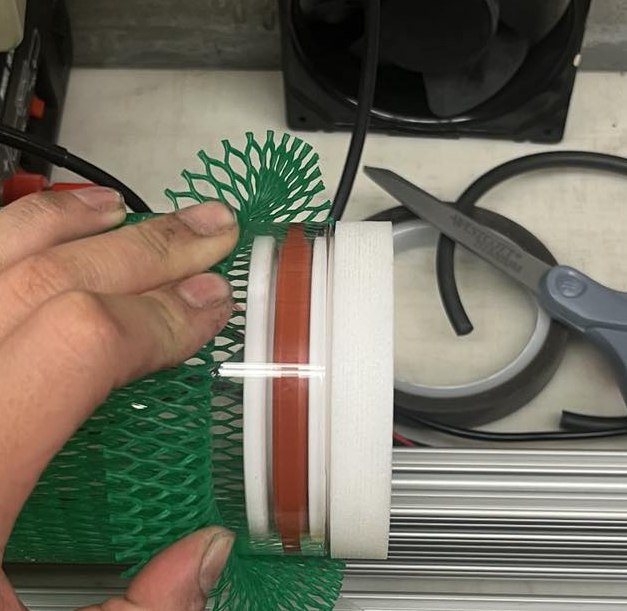
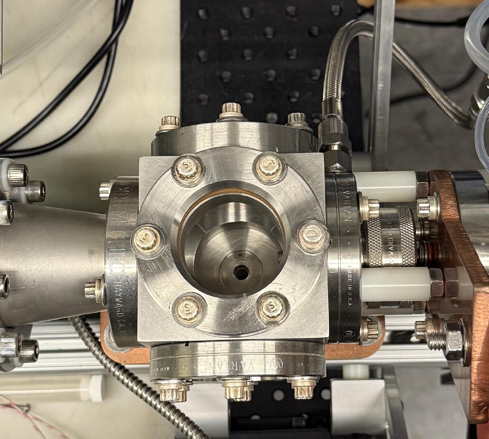
I machined vacuum adapters so the system can be evacuated and filled with argon. A graphite tube furnace feeds molten metal into the nozzle block.
02 · PSFC Gas Atomizer
Results: powder from four copper alloys
We atomized GRCop-42 and three new niobium-free copper alloys.
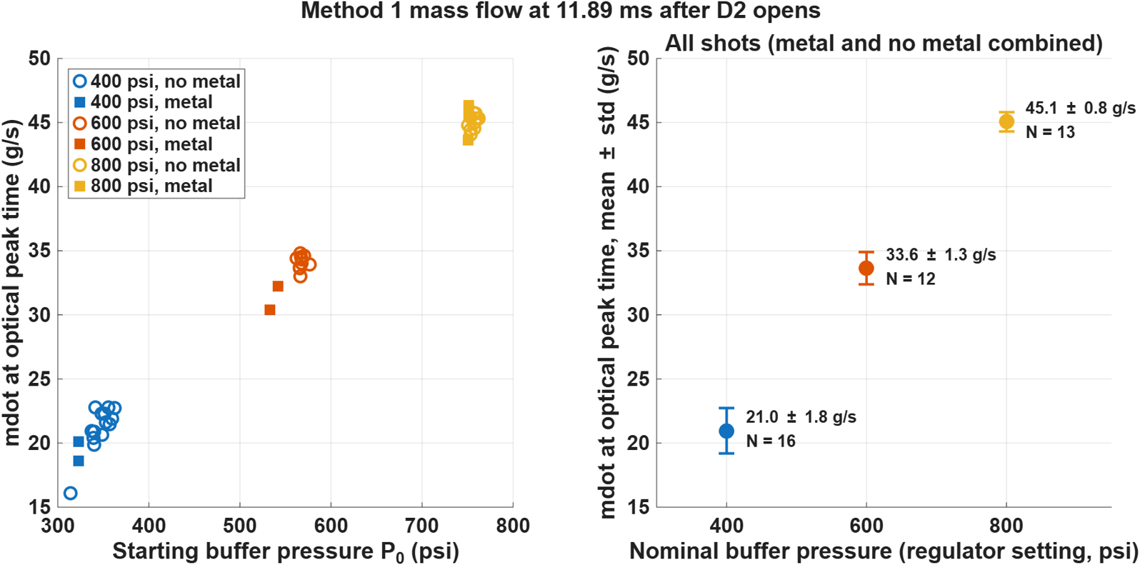
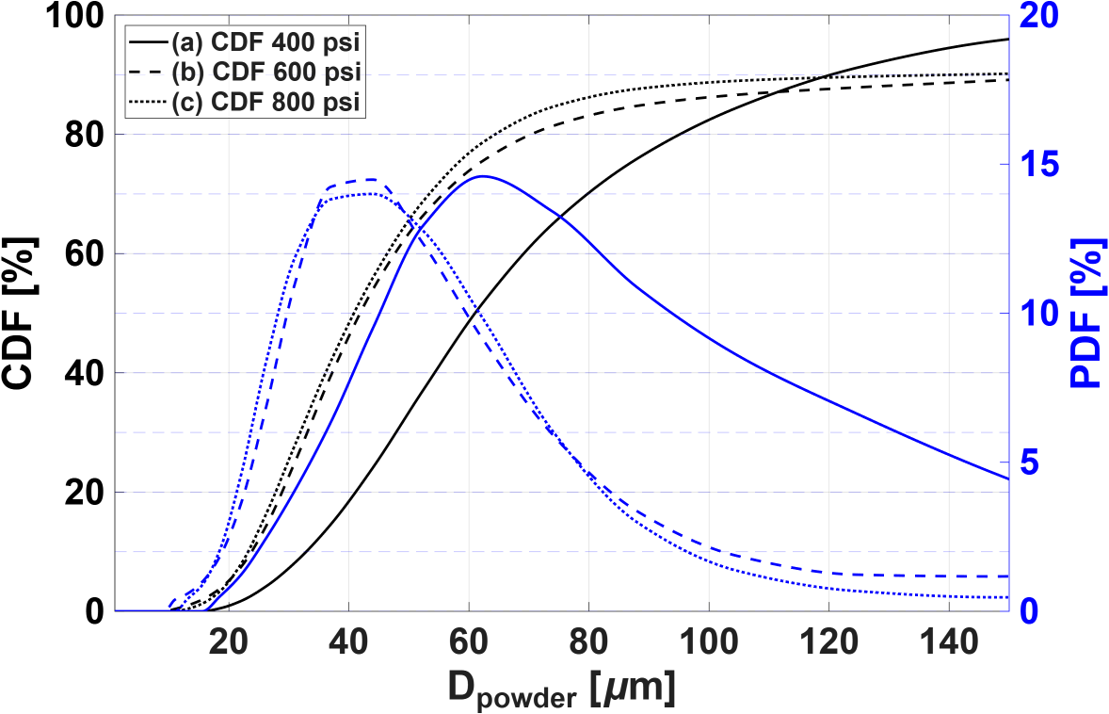
Raising gas pressure from 400 to 800 psi doubled gas flow (21 to 45 g/s) and made the powder finer: the most common particle size fell from about 60 to 40 µm.


03 · MIT Motorsports · Formula SAE
Design of MY26 Battery Pack
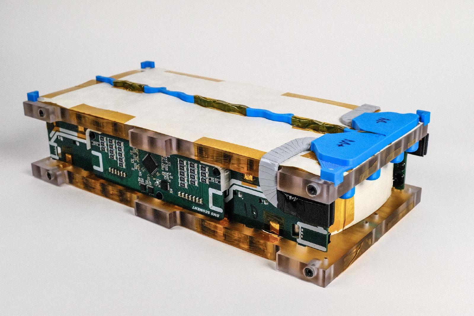
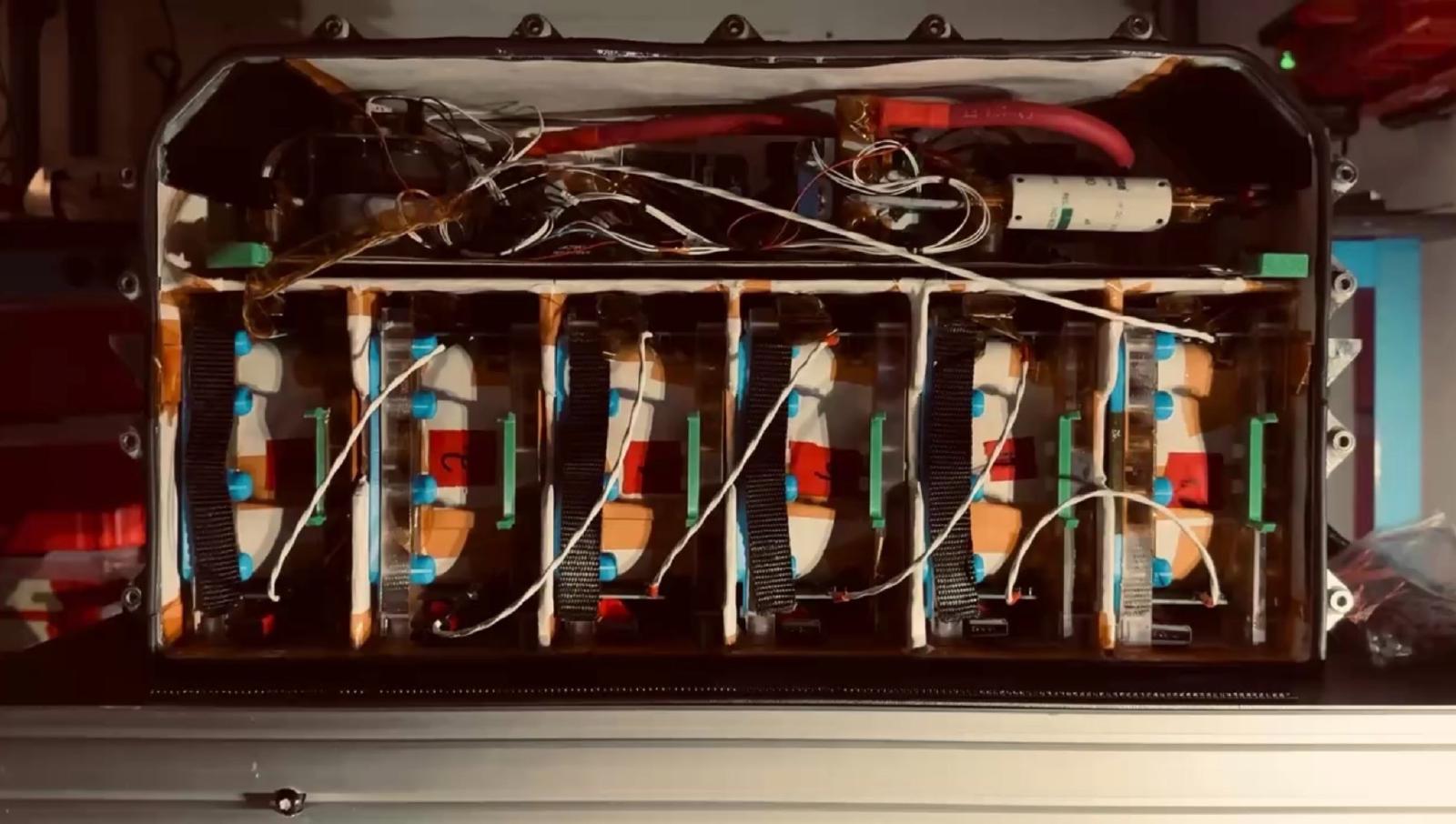
As battery co-lead, I led a team of five through the design and manufacturing of MIT Motorsports’ first 600 V pack, which delivers the full 80 kW competition limit. It is the most efficient and energy-dense battery in team history (142 Wh/kg), the first that needs no liquid cooling, and sits in the team’s first carbon fiber battery box.
My contribution
- Led sizing, design and manufacturing of the 600 V, 432-cell pack
- Spearheaded the module design and designed the team’s first composite battery structure
- Developed thermal and energy models that predicted the pack within 10% over the 22 km endurance race
03 · FSAE Battery
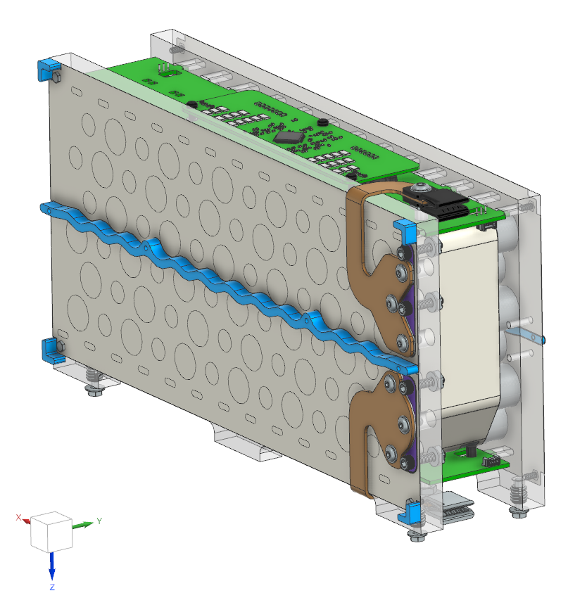
Module design: equal current through every cell
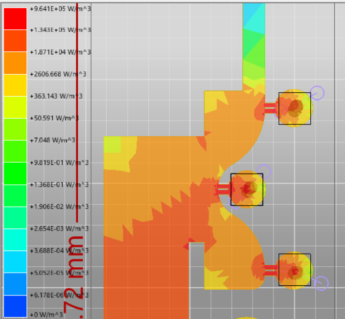
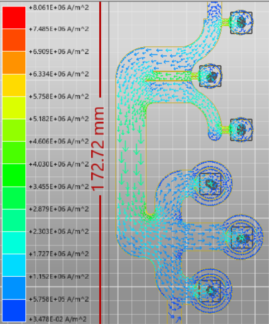
A cell that carries more current heats and ages faster, and limits the whole pack.
In a plain nickel strip, the middle cell has the shortest path and takes the most current. Slits in a branched strip balance every cell’s path; current-density simulations confirmed the fix.
03 · FSAE Battery
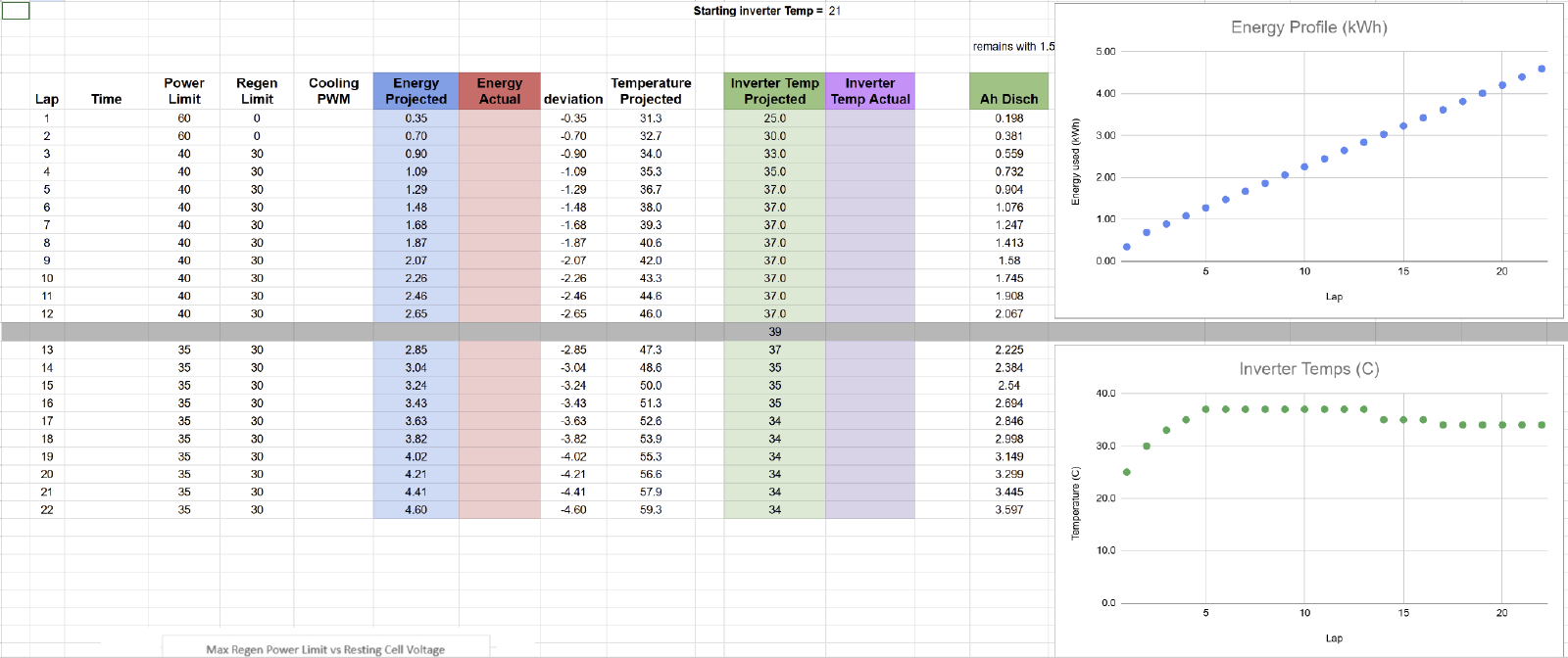
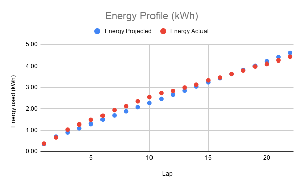
Predicting endurance, lap by lap
Cell testing fed a lap simulation that chose the pack layout and race strategy.
Our spreadsheet turns each lap’s power and regen limits into projected energy and temperatures. At the race, our models predicted the pack’s temperature and state of charge within 10% over 22 km of racing.
04 · MIT JARVIS Challenge · De Florez Award, 1st Prize
Mean-Line and Compressor Design for a 3D-Printed Turbojet
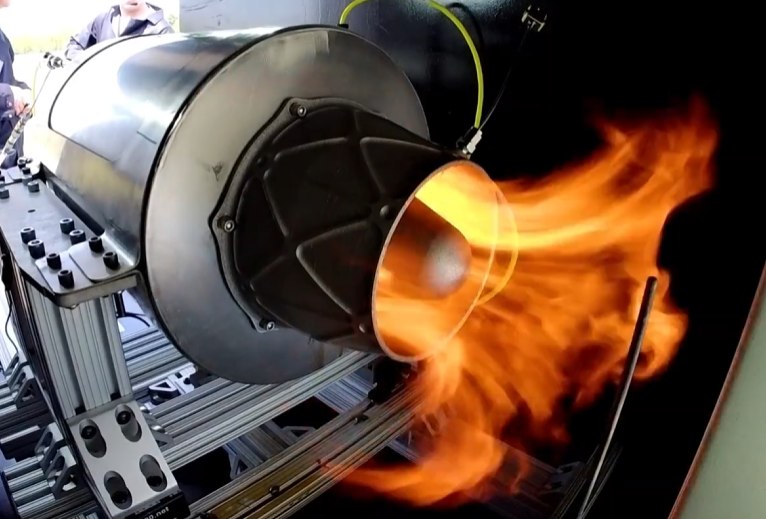
Our five-person team designed, built and tested a 100 lbf turbojet from a clean sheet in one semester, winning 1st prize for undergraduate design at MIT Mechanical Engineering’s de Florez Awards. I led the engine’s cycle analysis and its mean-line and compressor design. The engine started on propane and transitioned to Jet-A before a rotor lock ended testing just short of steady state.
My contribution
- Led the cycle analysis in GasTurb, setting pressure ratio, mass flow and burner temperature
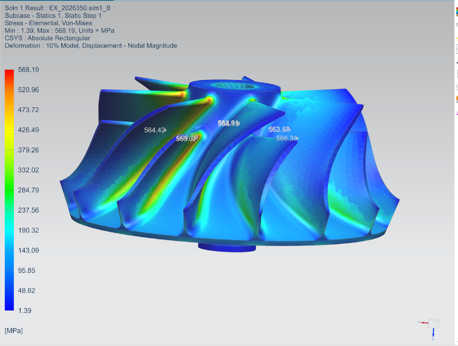
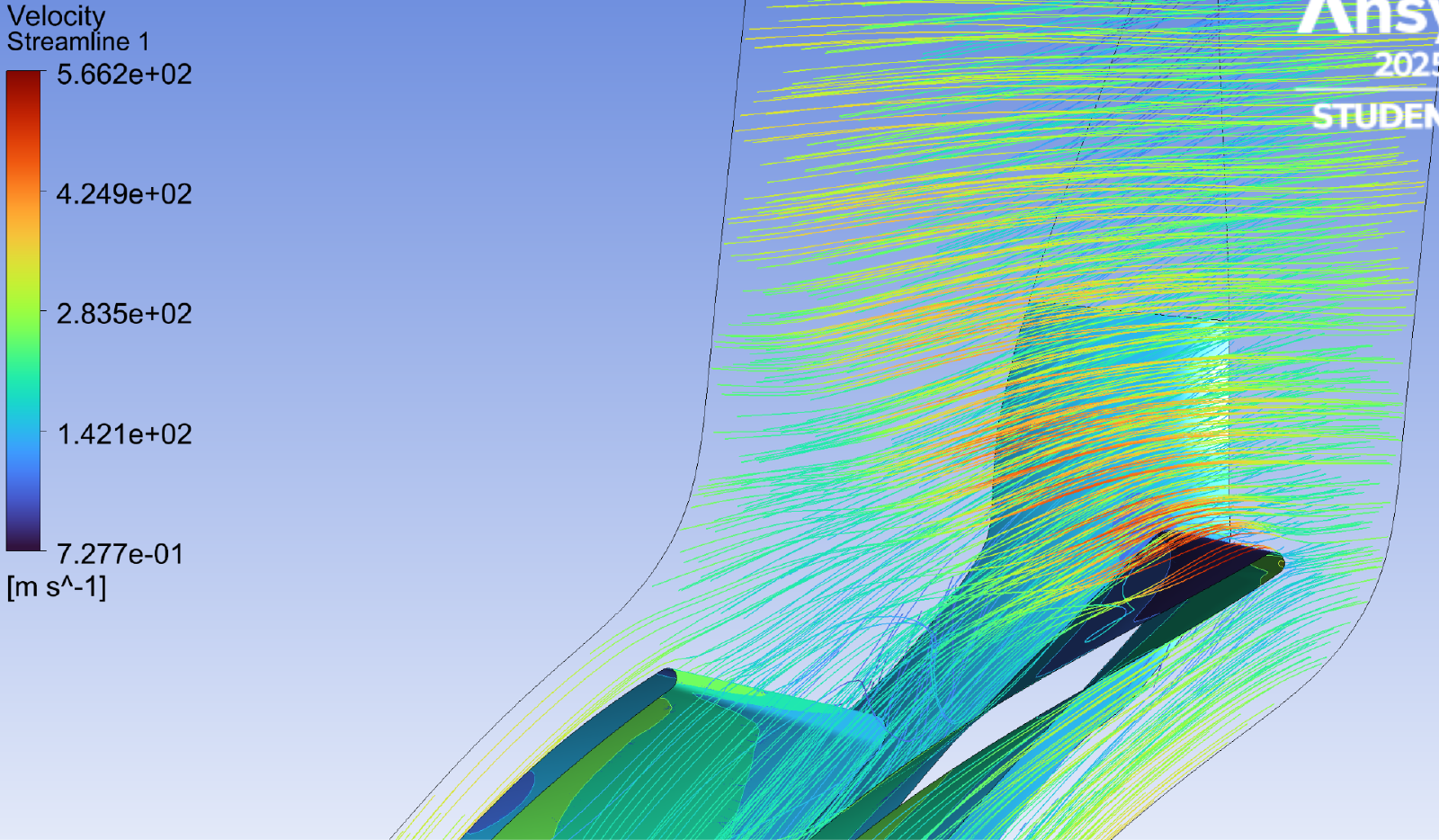
- Designed the centrifugal compressor in Concepts NREC and sized it with FEA and CFD
- Fabricated and tested a subscale combustor and balanced the rotor with the team
04 · JARVIS Turbojet
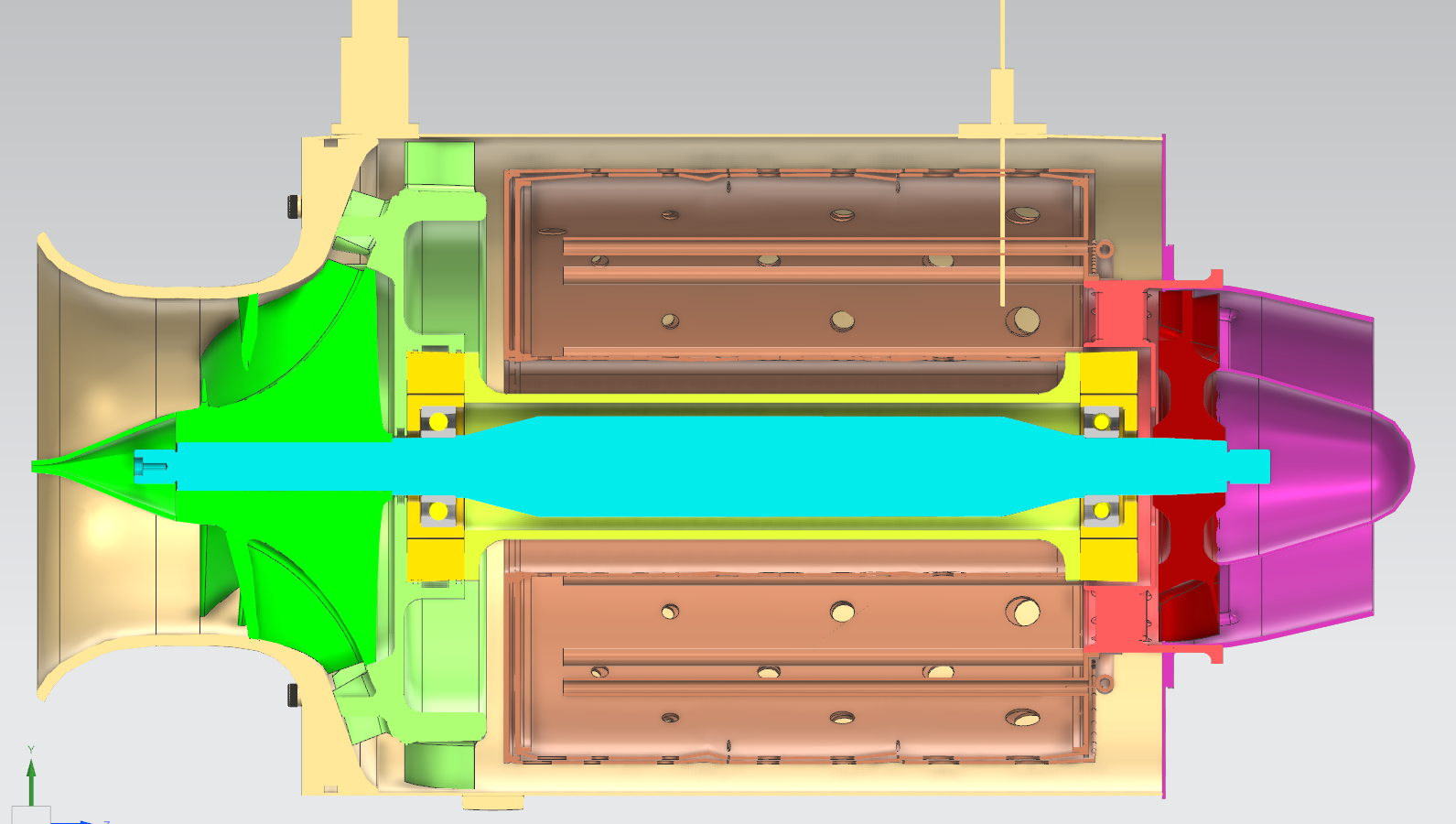
Setting the design point and designing the compressor
Every component has to agree on one operating point before any part can be designed.
- Cycle analysis set a pressure ratio of 3 and a 1100 K turbine inlet to meet the thrust and efficiency targets
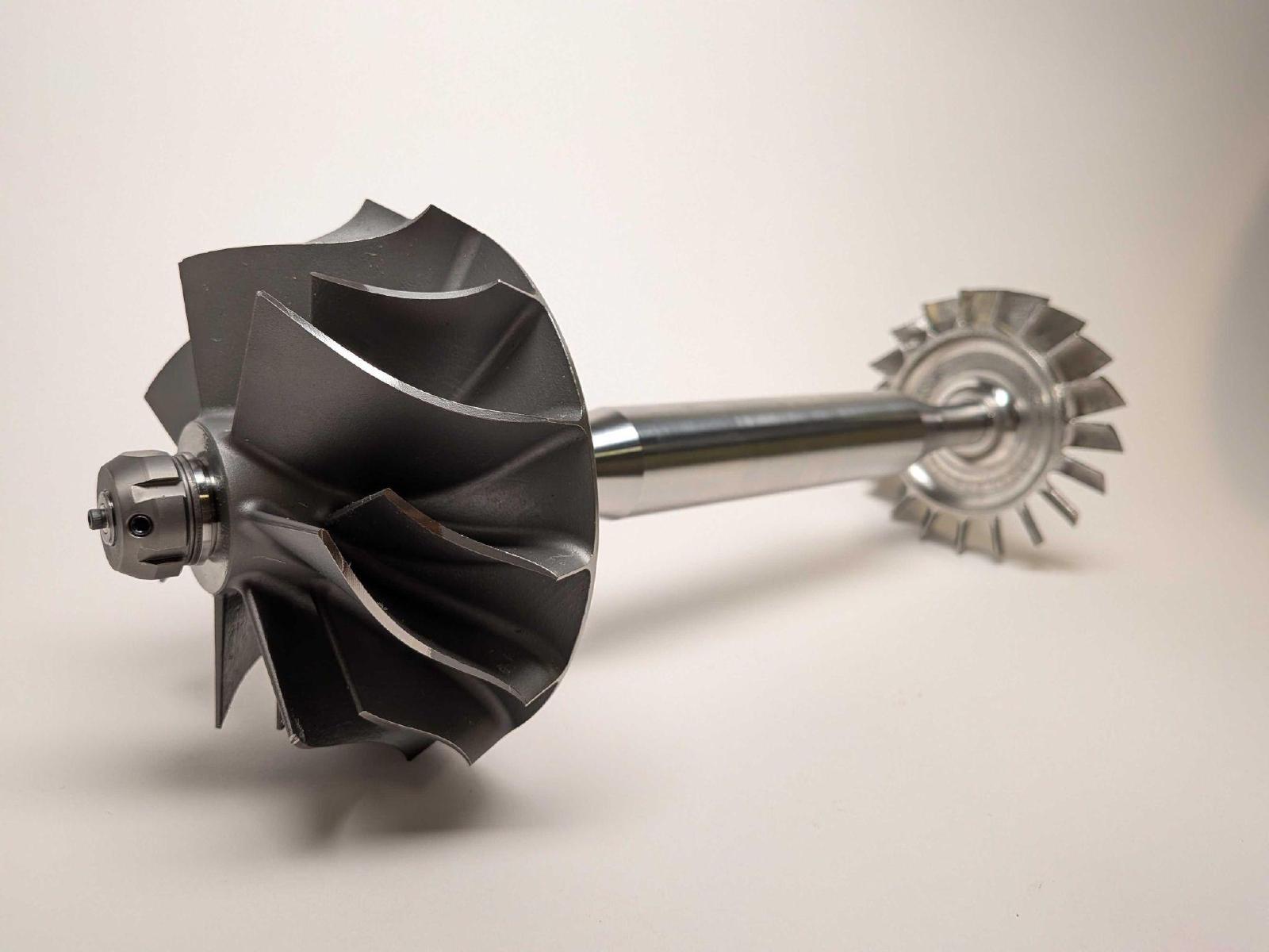
- The single-stage centrifugal compressor is 3D-printed titanium, 79% efficient, and checked for strength and stall at 65,000 rpm
04 · JARVIS Turbojet
Built in house, tested, and what went wrong
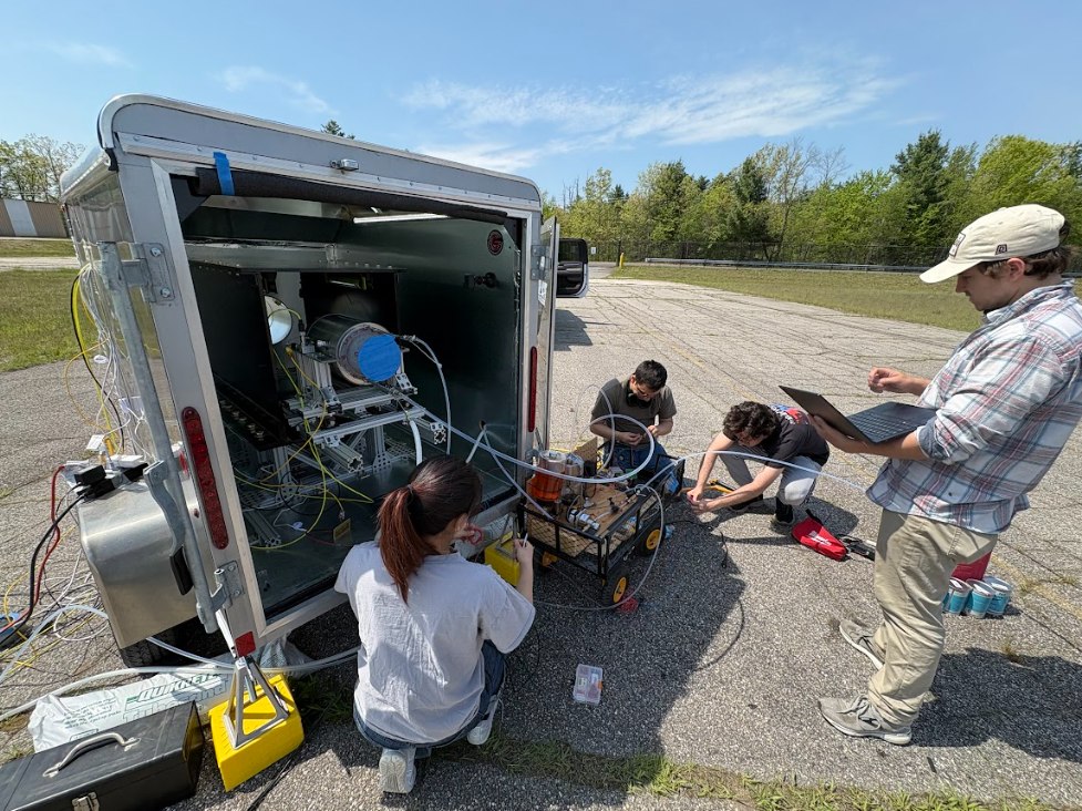
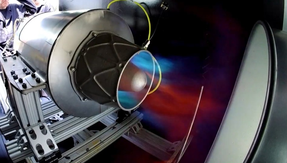
We fully manufactured a subscale combustor, which lit on its first fire test, and balanced the rotor ourselves.
In hot-fire tests the engine started consistently on propane and transitioned to Jet-A, but a rotor lock ended tests just short of steady state. We traced it to thermal expansion closing the labyrinth seal’s clearance.
Lesson: size clearances for hot running conditions, not just cold assembly.