Gas Atomization System (Part 1: Prototyping)
Research with MIT Plasma Science Fusion Center

- Mia Chen
- 3 min read
Introduction
This Spring (and the coming summer and fall), I’m working with the Plasma Science Fusion Center at MIT to develop a gas atomization system that will enable the research and development of new materials for the additive manufacturing of fusion reactor components.
Additive Manufacturing in Fusion Research
Additive manufacturing of fusion reactor components relies on a method called laser powder bed fusion, in which a thin layer of powder—typically a metallic alloy—is dispersed over a build plate and selectively sintered or melted by a high-power laser. This layer is then lowered and powder is repeatedly brushed over and solidified until a complete three dimensional component is produced. The alloys used for LPBF are typically produced through a method called gas atomization , in which a supersonic stream of inert gas, typically argon or helium, impacts a stream of molten metal, transferring kinetic energy and resulting in the breakup of the metal into microscopic droplets that cool and solidify as they fall.
Currently, the copper alloy most popularly used for these components contains NbCr2 precipitates which strengthen and improve the material properties of these alloys. However, the Niobium in this precipitate was discovered to readily absorb neutrons and become radioactive. The long term goal of my project is to develop a copper alloy fit for the additive manufacturing of nuclear fusion reactor components. To do this, I first need to develop a gas atomization system that enables the rapid production of small quantities of powder alloys, enabling us to protoype alloys without shelling out thousands of dollars and depending on lead times from commercial gas atomization suppliers.
Prototype nozzles
In order to successfully atomize the molten metal, we need a nozzle that can deliver gas at a sufficient velocity and mass flow rate to break the melt feed stream into consistently sized powder particles. To give us maximum control and flexibility in terms of the nozzle geometry, these nozzles are manufactured through SLA 3D Printing
First, I played around with different nozzle geometries and expansion ratios to see what overexpanded vs underexpanded looked like under our imaging system.
Then I incorporated the best geometry into a circular nozzle in which multiple jets are positioned around a central melt feed channel. I also tried an annular design in which the gas was delivered through a single continuous slit, but found that the gas was able to reach higher velocities with the discrete jet nozzles.
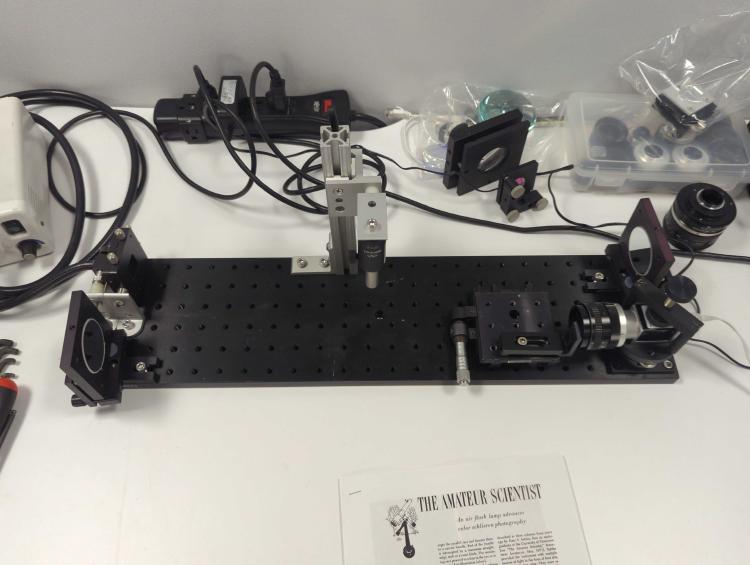
Schlieren Imaging system
The video above wouldn’t be possible without the schlieren imaging system we put together. In short, schlieren imaging relies on the varying refractive index of a fluid which is affected by its flow rate and other facturs like density, temperature, pressure.
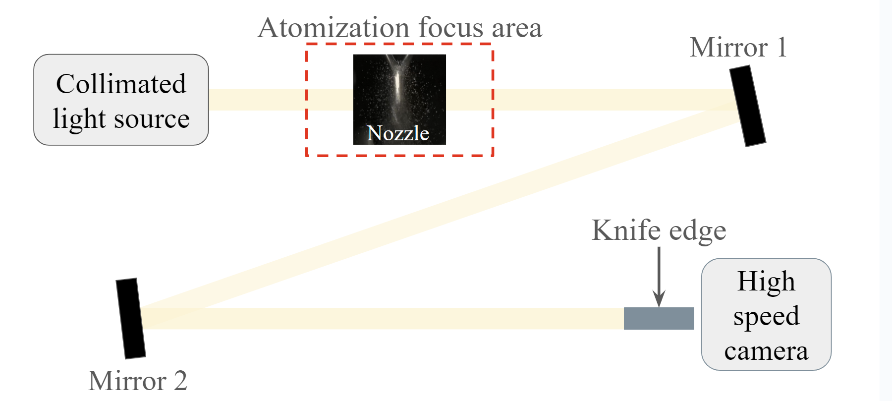
In our setup, a collimated light source shines through a “target area” where the atomization will be occurring, and then is reflected off of and focused by a pair of mirrors which focuses the light into a sharp and thin slit. This light is then blocked by a sharp “knife edge” obstruction in front of our high speed camera. When atomization occurs, the flow rates of the gas can then be seen because the changes in refactive index of the gas allow light to make it past the knife edge and be captured by the camera behind it.
Next Steps
Now that we’ve prototyped systems on the bench we are working toward designing and building the gas atomization system assembly. My labmate Mariabelle has been focusing on the furnace which will allow us to melt the metal before atomization, so the next steps are to integrate the nozzle and furnace components so we can start atomizing new materials!